Welcome to ServLifts Official Website

A dumbwaiter drawing is not a sales document. It is the thing your architect, your builder and your lift inspector all read before anyone cuts a hole in a wall. This page shows exactly which dumbwaiter drawings we issue, what we need from you before we can draw, and what we will not put our name on.
ServLifts builds traction food dumbwaiters in Wujiang, Suzhou, and issues a dumbwaiter drawing set with every unit. Below is the actual sample sketch for model SC-A005, the same one we send to a buyer who is still deciding.
Need it today? WhatsApp +86 180 6199 0305 with a photo of the shaft and a tape measure across the opening, or use the request form at the bottom of this page. Send the shaft dimensions, the number of stops and the load, and we will come back with dumbwaiter drawings for your shaft, normally within two working days.
- Three Documents, Three Different Jobs
- What Is on a Construction Sketch
- What We Need From You Before We Can Draw
- How the Drawing Changes With the Drive Type
- The Approval Loop: Three Rounds, Then It Is Frozen
- Seven Errors Caught at the Drawing Stage
- What We Do Not Provide
- How to Request Your Drawing Set
- Dumbwaiter Drawings FAQ
Three Documents, Three Different Jobs
Most buyers ask for “the dumbwaiter drawing” and receive a file that answers a different question than the one they had. There are three documents in a dumbwaiter drawing set, and they are not interchangeable.
| Document | Format | Who it is really for | When you get it |
|---|---|---|---|
| Construction sketch | PDF, one page | Your builder and your mason, to check that the shaft and opening will accept the machine | Before the order, free of charge |
| Layout drawing | PDF, fully dimensioned, with title block and revision letter | Your architect and the permit application | With the order, after the sketch is confirmed |
| CAD file | DWG and DXF | Your design team, to place the shaft and machine into the building model | After the layout drawing is approved |
The difference matters commercially. A construction sketch is a fit check, not a construction document: the dumbwaiter drawing that gets submitted is the layout drawing, and it carries the machine envelope and the clearances, but it is not sealed and it does not replace your architect’s details. The layout drawing is the one that gets submitted, and it is the one that must match the site as built. The CAD file exists for a single reason, which is that your design team should not be redrawing our machine from a PDF.
What Is on a Construction Sketch
The sample above is the dumbwaiter drawing we issue for SC-A005. It carries four things on one page: a section through the shaft and car, a plan at each landing showing the opening and the inspection window, an isometric of the shaft built in brick, and the specification strip along the bottom.
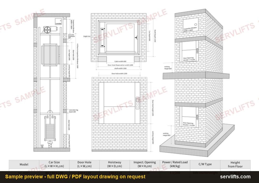
Sample preview of a ServLifts construction sketch. The full-resolution PDF and the DWG are issued with the order.
| Item on the drawing | SC-A005 |
|---|---|
| Car size (L × W × H) | 80 × 80 × 100 cm |
| Door hole (W × H) | 120 × 120 cm |
| Hoistway (W × D) | 130 × 110 cm |
| Inspection opening | 80 × 80 cm |
| Power / rated load | 1.1 kW / 200 kg |
| Counterweight position | Side |
| Height from floor | 70–80 cm |
Two of those numbers are read wrongly more often than any others. The door hole is not the rough opening. The 120 × 120 cm is the hole the door frame needs, measured to the outside of the frame, and the mason must build to it rather than to the shaft width. And the height from floor is a range, not a fixed dimension, because it depends on the finished floor level at the lower landing. If tile or screed is still to come, say so before the dumbwaiter drawing is issued, not after the frame is fixed.
The general envelopes for the rest of the range, from 50 kg up to the 300 kg custom build at 120 × 120 × 140 cm, are set out in our dumbwaiter dimensions and shaft size guide.
What We Need From You Before We Can Draw
Every drawing starts from six inputs. When one is missing, the dumbwaiter drawing is issued with an assumption on it, and assumptions are what revision two is made of.
| # | Input | Why it changes the drawing |
|---|---|---|
| 1 | Clear shaft width × depth, measured as built | Sets the car size, the counterweight position and the rail centres |
| 2 | Floor-to-floor height at every stop, plus total travel | Sets rope length, door heights and the machine position |
| 3 | Number of stops and which landings are served | Sets the number of doors, interlocks and landing plates |
| 4 | Load in kg, and what is carried | A tray, a trolley and a linen bag need different car floors and door widths at the same load |
| 5 | Door type and handing | Hinged, sliding or counterweighted, and which side the hinge falls on, decides the frame |
| 6 | Power available: voltage, phase, frequency, isolator position | Decides the panel and the wiring diagram, and cannot be corrected on site |
There is a seventh input that is not a dimension: the jurisdiction. A dumbwaiter drawing issued for a hotel in Manila and a drawing issued for a hotel in Minnesota carry the same machine and different paperwork, because the plan review requirements differ. Minnesota is a useful example of how specific it gets: state rule 1307.0030 makes it unlawful to install a dumbwaiter without a permit first, and requires plans and specifications to be submitted with the application, which means the layout drawing has to be finished before the work starts rather than alongside it.
The Minnesota elevator and related devices rules are worth reading in full for exactly that reason. Naming the city rather than the country saves a round. Our dumbwaiter specification guide covers what the machine must be built to; the dumbwaiter drawing is what proves it fits.
A photograph of the shaft with a tape measure held across the opening is worth more than a paragraph of description. If the shaft exists, measure it. If it does not exist yet, send the architectural section and tell us which dimensions are fixed and which are still concrete and blockwork.
How the Drawing Changes With the Drive Type
The same shaft produces four different dumbwaiter drawing sets depending on how the machine is driven. This is the decision that most often has to be revisited, because it is usually made after the shaft is built.
| Drive | What it needs above the shaft | What it needs below | What changes on the drawing |
|---|---|---|---|
| Traction, top-drive | Machine space with service access | Standard pit | Machine bed, rope path and lifting beam position |
| Traction, bottom-drive | Clearance for the car and its sheave only | Machine at the shaft base, larger footprint | Rope route reverses, and the base detail becomes the critical one |
| Manual, hand-crank or rope-pull | Headroom for the rope and pulley only | No pit required in most layouts | No power, no panel, different interlock set |
| No-pit | Depends on the drive above | Ramp or low sill instead of a pit | Landing detail and door sill change at every stop |
Where headroom is the constraint, the dumbwaiter drawing flips from a top-drive to a bottom-drive arrangement and the whole base detail is redrawn; our low headroom dumbwaiter page covers the four ways that is done and what each one costs in space. Where there is no power at all, the arrangement is a manual dumbwaiter and the drawing loses the panel, the travelling cable and the safety chain that goes with them.
The Approval Loop: Three Rounds, Then It Is Frozen
Every dumbwaiter drawing set we issue carries a revision letter, and three rounds is the normal path to a buildable drawing.
Round 1 — issued for comment. You, your builder and your architect mark it up. Most comments are dimensional. Round 2 — revised. Comments are incorporated and the drawing is re-issued with a new letter; this is the round where a shaft that measured differently from the plan gets corrected. Round 3 — issued for construction. The geometry is frozen. After that, a change is a change order: it costs money, it costs time, and on an export project it can cost a second shipment.
Two of those three rounds usually happen because a dimension was taken from a dumbwaiter drawing instead of from the site. The cheapest way to reach round three in one week is to send measured dimensions in the first message. The drawing is one document in a pack, though, and a consultant will ask for the rest on the same day — what a complete dumbwaiter submittal contains lists all twelve.
Seven Errors Caught at the Drawing Stage
These seven repeat across projects, and all of them are visible on the dumbwaiter drawing before anything is cut.
1. The rough opening is dimensioned from the shaft, not from the door frame. The frame is the fixed item. Build the opening around the frame drawing and check the diagonal, not just the width and height.
2. The pit depth comes from the architectural section. That section shows the structural slab, not the finished floor. A 100 mm screed turns a correct pit into a shallow one.
3. The overhead clearance is measured to a beam that later moves. Services coordination lowers beams. Measure overhead to the lowest obstruction as it will be when the machine arrives.
4. The landing finished floor level is left “to be confirmed”. It is the dimension that decides the sill, and it is the one nobody wants to commit to. Commit to it before the frame is fixed.
5. The door swings into a corridor that has a fire door in it. Two doors, one corridor, and neither drawing shows the other. Mark the swing on the layout drawing and check it against the escape route.
6. The power is drawn three-phase and ordered single-phase. The panel cannot be corrected on site. Put voltage, phase, frequency and protective device rating in one written line from the electrician.
7. There is no lifting point above the shaft. The machine and the rails then get manhandled, and alignment suffers for the life of the unit. A beam or a hoist is a building item and has to be on the dumbwaiter drawing.
Each of these errors also appears in the field, in the same order, in our dumbwaiter installation process guide, which is worth reading before you approve the dumbwaiter drawing rather than after.
What the crew tests once the drawing is built is set out in our dumbwaiter commissioning guide.
What We Do Not Provide
Four items are outside what a manufacturer’s drawing set can honestly deliver. A supplier who says yes to all four is not being helpful; he is postponing the conversation.
We do not stamp or seal dumbwaiter drawings for your jurisdiction. A sealed drawing has to come from an engineer licensed where the building is. We will review and revise to his comments, and we will not pretend to be him.
We do not design your building. The shaft, its structure, its fire rating and its foundations belong to the building. We design the machine and the interface to it: rails, brackets, sill, landing fixings.
We do not certify the fire rating of the shaft or the landing door. That is a building detail and is tested as one. The regime that follows the machine once it is in use is a separate question again: in the UK, thorough examination at risk-based intervals is required by LOLER, and the HSE guidance on lift equipment is what an inspector works from.
We do not survey the site. We work from your measurements and photographs. When a shaft is irregular enough that a survey is needed, we will say so instead of guessing on the dumbwaiter drawing.
How to Request Your Drawing Set
Send three things and we come back with a construction sketch for your shaft, normally within two working days.
One: the clear shaft dimensions and the floor-to-floor heights. Two: the number of stops and the load, in kilograms and in what it carries. Three: the destination country and city, because that decides which paperwork the dumbwaiter drawing has to satisfy.
If you already have a shaft drawing from your architect, send it as well. We will mark it up rather than start again, and you will see immediately which dimensions are the ones that bind.
For a WhatsApp conversation instead of a form, the number is at the top of this page: +86 180 6199 0305. A photograph of the shaft with a tape measure in frame is usually enough for us to tell you which model fits.
Dumbwaiter Drawings FAQ
Do you charge for the dumbwaiter drawings?
The one-page construction sketch is free and does not commit you to an order. The dimensioned layout drawing and the CAD file are issued with the order, because they are the documents the machine is built from.
Can you work from my architect’s drawing?
Yes, and it is the fastest route to a workable dumbwaiter drawing — but we will still ask you to confirm the as-built shaft dimensions. Architect’s drawings describe the building as designed; the machine has to fit the building as built.
Can I get the DWG before I order?
No. The DWG is the file your design team builds the shaft around, and once it is in a building model it is difficult to walk back. We send a dimensioned PDF sketch instead, which answers the same fit question.
What if my shaft does not match any standard model?
Then it becomes a custom build. The standard range runs from 50 kg to 300 kg, and the 300 kg unit is a custom envelope of 120 × 120 × 140 cm rather than a catalogue size. A shaft that is too narrow for a standard car is usually still buildable — the car gets narrower before the shaft gets wider.
How long does a dumbwaiter drawing take?
The construction sketch is normally two working days from the three inputs above. The dimensioned layout drawing follows three to five working days after the order is confirmed, and revisions inside the approval loop are usually turned around the same week.
Ready to start? Send the shaft dimensions, the number of stops and the load through our contact page, and we will reply with the sketch and the model that fits. ServLifts builds in Wujiang, Suzhou, China.