Welcome to ServLifts Official Website

Dumbwaiter Installation Guide: Shaft Preparation, Dimensions & Step-by-Step Process
Complete dumbwaiter installation guide covering shaft preparation, wall opening dimensions, electrical requirements, and a 7-step mounting process for restaurants and hotels.

Why Proper Dumbwaiter Installation Matters
A dumbwaiter can transform how your restaurant, hotel, or commercial kitchen handles vertical transport. But even the best CE-certified dumbwaiter will underperform if the installation is rushed or poorly planned. A correct installation ensures smooth operation, extends equipment lifespan, and most importantly, keeps your staff safe.
In this comprehensive dumbwaiter installation guide, we walk you through every phase — from shaft preparation and wall dimensions to electrical requirements and the step-by-step mounting process. Whether you are installing a 100kg side counterweight dumbwaiter or a 250kg rear counterweight model, this guide covers what you need to know.
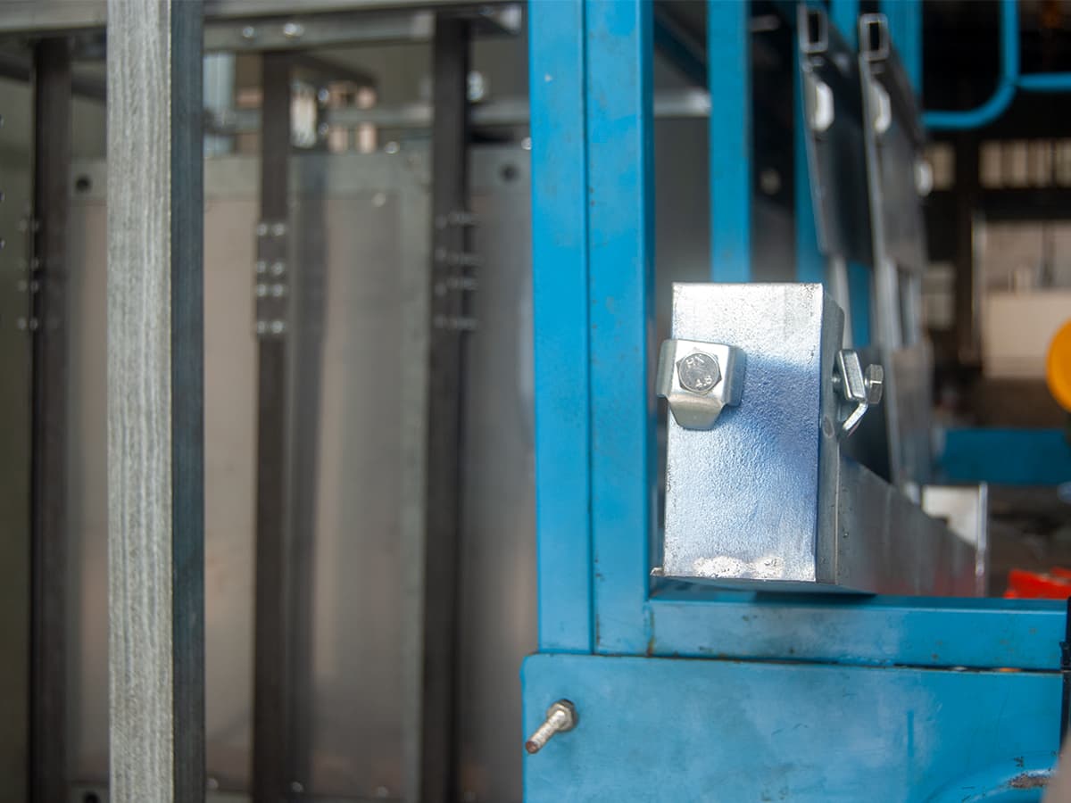
Pre-Installation Preparation
Site Survey and Measurement
Before anything else, conduct a thorough site survey. You need to verify:
- Floor-to-floor height — Measure the vertical distance between each landing where the dumbwaiter will stop. This determines the guide rail length and traction machine placement.
- Available wall space — Ensure the wall can accommodate the shaft opening plus the frame thickness (typically 50–100 mm on each side).
- Load-bearing capacity — The wall or structure supporting the guide rails must handle the dynamic loads of a fully loaded car plus counterweight.
- Access for maintenance — Leave at least 600 mm of clearance on the access side for inspection and repairs.
Shaft Construction Requirements
The shaft (also called the hoistway) is the vertical passage through which the dumbwaiter travels. Key requirements include:
| Parameter | Minimum Requirement | Recommended |
|---|---|---|
| Shaft width (interior) | Car width + 100 mm | Car width + 150 mm |
| Shaft depth (interior) | Car depth + 80 mm | Car depth + 120 mm |
| Wall thickness | 200 mm brick or 150 mm concrete | 240 mm brick or 200 mm concrete |
| Shaft plumbness tolerance | ±5 mm per 3 meters | ±3 mm per 3 meters |
| Surface finish | Plastered and smooth | Painted, no protrusions |
Wall Opening Dimensions
Each landing entrance requires a precisely cut opening in the shaft wall. The standard opening dimensions for ServLifts dumbwaiters are:
- 100kg models (60×60×80 cm): Opening 700 × 700 mm
- 200kg models (80×80×100 cm): Opening 900 × 900 mm
- 250kg models (100×100×120 cm): Opening 1,100 × 1,100 mm
Always confirm the exact opening size with your dumbwaiter manufacturer before cutting, as frame designs vary between side counterweight and rear counterweight configurations. For a deeper comparison of these two types, see our side counterweight vs rear counterweight guide.
Electrical and Infrastructure Requirements
Power Supply Specifications
ServLifts dumbwaiters operate on standard single-phase or three-phase power, depending on the model:
| Model Capacity | Voltage | Phase | Motor Power | Breaker Rating |
|---|---|---|---|---|
| 100 kg | 220V / 230V | Single-phase | 0.75 kW | 16A |
| 200 kg | 220V / 380V | Single or three-phase | 1.1 kW | 20A |
| 250 kg | 380V | Three-phase | 1.5 kW | 25A |
A dedicated circuit breaker is mandatory. Do not share the circuit with other kitchen equipment — voltage fluctuations can cause the control board to malfunction.
Control Wiring
Each landing station requires a call button and a landing indicator. The standard wiring uses a multi-core cable (7-core or 12-core, depending on the number of stops) running through PVC conduit inside the shaft. Keep control wiring at least 300 mm away from the power cable to prevent electromagnetic interference.
Step-by-Step Installation Process
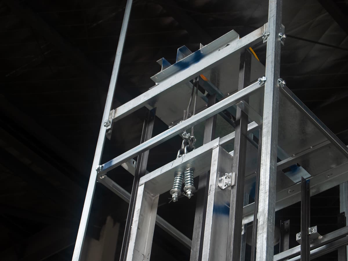
Step 1: Mount the Bottom Frame
Bolt the bottom frame to the floor of the shaft using M12 anchor bolts. Use a spirit level to ensure the frame is perfectly horizontal — any deviation here will compound as you install the guide rails. Torque all bolts to 45 Nm.
Step 2: Install the Guide Rails
Guide rails are typically supplied in 3-meter sections. Bolt each section to the wall brackets using rail clips, starting from the bottom and working upward. After every section, check plumbness with a laser level. The maximum allowable deviation is 0.5 mm per meter of height.
Step 3: Assemble the Carriage (Car)
Lower the carriage into the shaft from the top landing. Attach the guide shoes to the rails, then connect the traction ropes (for traction-type) or chain (for chain-type dumbwaiters). Ensure the car sits level — adjust the guide shoe tensioners until the car moves smoothly without lateral play.
Step 4: Install the Counterweight
The counterweight is positioned either beside the car (side counterweight) or behind it (rear counterweight). Connect the counterweight to the traction ropes, ensuring the rope tension is equalized. The counterweight should travel smoothly along its own guide rails.
Step 5: Mount the Traction Machine
Bolt the traction machine to the top of the shaft (or to a dedicated machine room platform). Align the sheave groove with the rope path — misalignment here causes rapid rope wear. Connect the motor to the control panel using the wiring diagram provided by the manufacturer.
Step 6: Wire the Control Panel
Mount the control panel at the top landing (or in a designated machine room). Connect:
- Motor power cables (U, V, W for three-phase; L, N for single-phase)
- Limit switches (top and bottom overtravel protection)
- Call buttons and landing indicators at each stop
- Door interlock switches (safety circuit)
- Earth ground connection (mandatory)
Step 7: Testing and Commissioning
Before handing over, perform the following tests:
- Empty car test — Run the car up and down through all stops. Check for unusual noise, vibration, or jerky movement.
- Load test — Place 125% of rated capacity in the car and run one complete cycle. The motor should not stall, and the brake must hold the car stationary at any position.
- Limit switch test — Manually trigger the top and bottom limit switches to verify they cut power immediately.
- Door interlock test — Attempt to call the car while a landing door is open. The car must not move.
- Emergency stop test — Press the emergency stop button at each landing to verify it halts the car instantly.
Common Installation Mistakes to Avoid
Even experienced contractors make errors. Here are the most frequent ones we see:
- Skimping on shaft plumbness — A shaft that is 10 mm out of plumb over 6 meters will cause guide shoe wear within months. Fix the shaft before installing.
- Undersized power supply — Sharing a circuit with a commercial dishwasher caused voltage dips that reset the control board. Always run a dedicated line.
- Skipping the load test — Some installers test with an empty car only. Always test at 125% rated load before signing off.
- Improper rope tension — Unequal tension causes one rope to bear most of the load, leading to premature failure. Use a tension gauge.
- Neglecting door interlocks — A missing or bypassed door interlock is a serious safety violation. Every landing door must have a functioning interlock.
Installation Timeline and Cost
For a standard 2-stop dumbwaiter installation, expect the following timeline:
| Phase | Duration | Notes |
|---|---|---|
| Shaft preparation | 1–3 days | Depends on wall construction |
| Electrical rough-in | 0.5 day | Dedicated circuit + conduit |
| Equipment installation | 1 day | Frame, rails, car, machine |
| Wiring and control | 0.5 day | Panel, buttons, interlocks |
| Testing and commissioning | 0.5 day | Full load + safety tests |
| Total | 3–5 days | For a straightforward 2-stop unit |
For a breakdown of equipment costs, see our complete dumbwaiter cost guide. ServLifts provides detailed installation drawings and remote technical support for all orders, ensuring your contractor has everything needed for a smooth install.
Frequently Asked Questions
Can I install a dumbwaiter myself?
No. Dumbwaiter installation requires electrical work, structural modifications, and safety system commissioning. Always use a licensed contractor. ServLifts provides installation drawings and remote guidance to support your installer.
How thick does the shaft wall need to be?
The shaft wall should be at least 200 mm for brick or 150 mm for reinforced concrete. This ensures sufficient strength to hold the guide rail brackets and absorb operational vibrations.
What power supply do I need for a dumbwaiter?
Most 100kg dumbwaiters run on standard 220V single-phase power. Larger 250kg models may require 380V three-phase. Always check the specification sheet for your specific model.
How long does dumbwaiter installation take?
A standard 2-stop dumbwaiter installation takes 3–5 days, assuming the shaft is already prepared. Complex multi-stop installations or retrofits may take 1–2 weeks.
Do I need a permit to install a dumbwaiter?
Building permits are required in most jurisdictions. Check with your local building authority. ServLifts provides CE certification and technical documentation to support permit applications.
[…] repairs in a single visit, rather than waiting days for parts to ship. If you are planning a new dumbwaiter installation, ask your supplier to include a starter spare parts kit with the […]
[…] × 1500mm is recommended for most standard models. For step-by-step guidance, see our detailed dumbwaiter installation guide covering shaft preparation, dimensions, and the full installation […]
[…] complete guidance, refer to our comprehensive installation guide, which covers shaft preparation, dimensions, and the step-by-step installation […]
[…] labor-intensive but also disrupted the quiet and elegant dining atmosphere of banquets. Learn how modern installation preserves this […]
[…] of correct equipment usage, and helps avoid irregular and risky operational behaviors. Refer to our installation guide for setup […]
[…] work — shaft walls, door openings, power supply — is usually the critical path. See the dumbwaiter installation guide for shaft preparation checklists and […]