Welcome to ServLifts Official Website

Dumbwaiter Installation Guide 2026: Requirements, Dimensions & Costs for Restaurants and Hotels

Installing a dumbwaiter in a restaurant or hotel is not as simple as ordering a unit and plugging it in. The success of any dumbwaiter installation depends on getting three things right before you even place an order: shaft dimensions, load capacity, and site readiness. This dumbwaiter installation guide follows the order real projects follow. Miss any of these, and you risk delays, budget overruns, or a lift that cannot do what you actually need it to do. This installation guide walks you through every requirement — whether you are building new or retrofitting into an existing building.
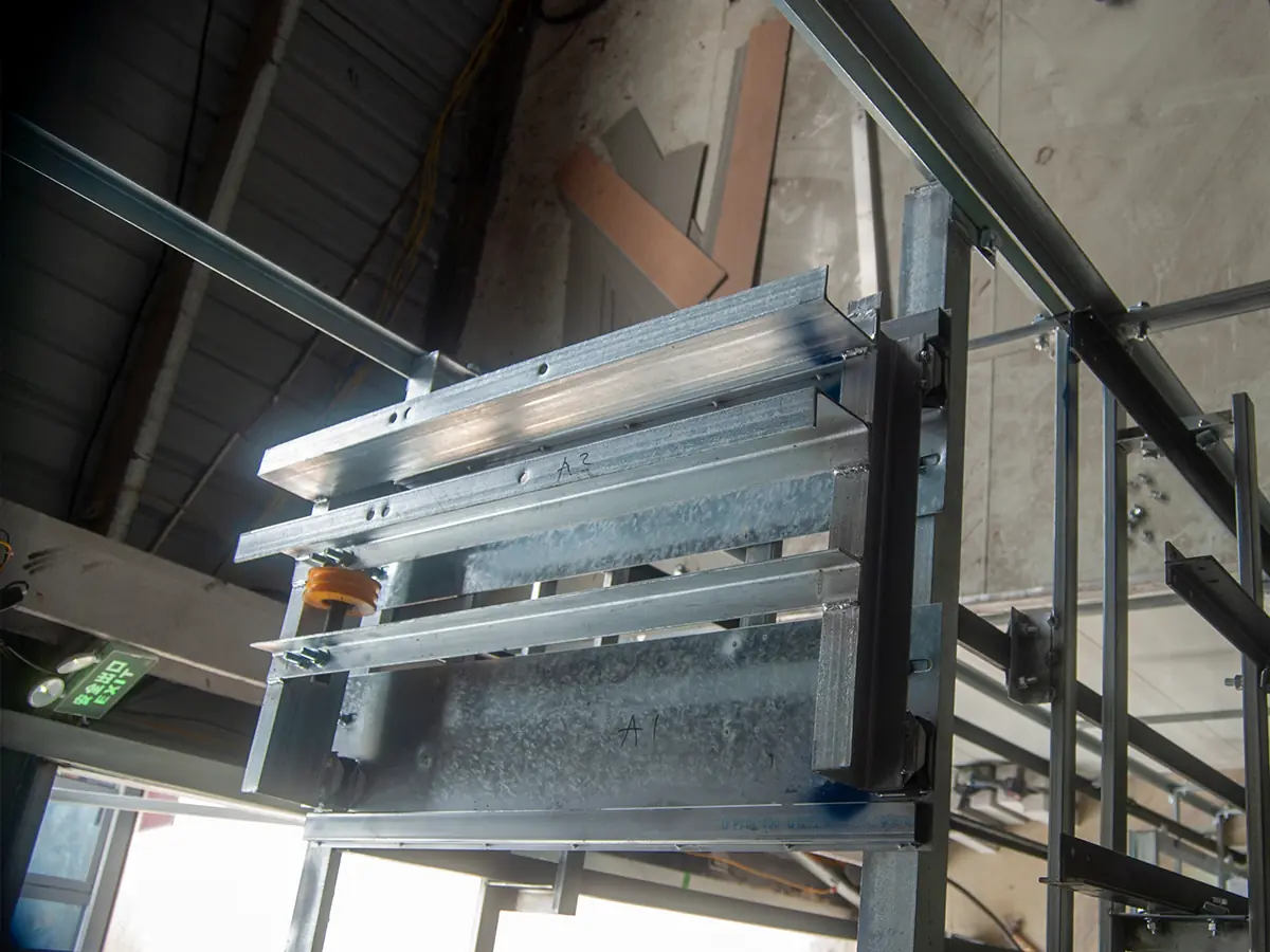
Dumbwaiter Shaft Size Requirements: The Numbers That Matter
The first technical question in any dumbwaiter installation project is: what are the dumbwaiter shaft size requirements for your building? The answer depends on the cabin dimensions you need, which in turn depend on what you plan to carry.
Here are the typical shaft dimensions for standard configurations:
| Cabin Size (W×D×H mm) | Shaft Size (W×D mm) | Typical Application |
|---|---|---|
| 600 × 600 × 800 | 850 × 850 | Document lift, small office |
| 700 × 700 × 1000 | 950 × 950 | Small cafe kitchen |
| 800 × 800 × 1200 | 1050 × 1050 | Standard restaurant food lift |
| 1000 × 1000 × 1200 | 1250 × 1250 | Hotel pantry lift, laundry dumbwaiter |
| 1200 × 1200 × 1400 | 1450 × 1450 | Heavy-duty hotel/laundry service lift |
Headroom and pit depth are often overlooked but equally critical. A standard traction dumbwaiter requires approximately 2,600–3,000 mm of headroom above the top floor and a pit depth of 300–500 mm below the bottom floor. Some self-supporting models reduce these requirements, but you should confirm exact numbers with your manufacturer before starting any construction work.
Self-supporting vs. shaft-dependent: Some dumbwaiters come with their own structural frame and do not need a load-bearing shaft wall. This can save significant construction cost, especially when retrofitting into an existing building. If your building does not have a dedicated shaft, look for a self-supporting model. If you are building a new shaft, budget for fire-rated walls and structural reinforcement, which can add $3,000–$8,000 to the project cost.
Retrofit considerations: Installing a dumbwaiter into a 1915 farmhouse or a century-old building is not the same as putting one into new construction. Older buildings may have irregular floor heights, thick masonry walls, limited electrical capacity, or no suitable vertical chase. A site survey by a qualified technician is non-negotiable for retrofit projects. For more context on retrofitting, see our guide on how to choose a dumbwaiter for restaurant and hotel which covers the full decision-making process.
Dumbwaiter Load Capacity Guide: Choosing the Right Rating
A dumbwaiter load capacity guide is something every buyer should consult before comparing prices. Choosing the wrong capacity leads to one of two problems: you either overpay for capacity you do not need, or you under-spec and the lift cannot handle your daily workload.
Here is a practical capacity reference based on real-world use cases:
| Load Capacity | Typical Use | Daily Cycles |
|---|---|---|
| 50–100 kg | Documents, small trays, residential laundry | 10–30 |
| 100–200 kg | Restaurant food trays, plates, small hotel pantry | 50–100 |
| 200–300 kg | Hotel laundry, bulk linen, heavy kitchen supplies | 80–150 |
| 300–500 kg | Hospital supplies, bulk goods, large hotel operations | 100–200 |
Why not just buy the largest capacity? Higher capacity means a larger motor, heavier guides, a bigger shaft, and more expensive components. A 300 kg unit costs substantially more than a 100 kg unit — not just for the equipment, but for the larger shaft construction and more powerful electrical supply. Only pay for what you need.
Pro tip from real installations: Restaurant owners frequently underestimate their tray stack height. A stack of four standard trays with food can easily measure 400–500 mm tall. Make sure your cabin interior height accommodates your maximum load — not just the weight, but the physical dimensions.
Electrical Requirements for Dumbwaiter Installation
Dumbwaiters are not plug-and-play appliances. They require dedicated electrical circuits, and the wrong voltage assumption can delay installation by weeks. Here is what you need to confirm:
Standard power configurations:
– 220V single-phase: Common for smaller residential and light commercial units (up to 100 kg). Most home installations use this configuration.
– 380V three-phase: Required for most commercial traction dumbwaiters (100 kg and above). Standard in restaurant and hotel installations.
– Control voltage: Typically 24V DC for the control system, stepped down from the main supply.
Site readiness checklist for electrical:
– Confirm available voltage and phase before ordering — manufacturers can usually accommodate either, but you need to specify upfront.
– Dedicated circuit: do not share the dumbwaiter circuit with kitchen equipment or laundry machines.
– Emergency stop circuit: must cut power independently of other building systems.
– Intercom and lighting: cabin lighting and intercom systems run on low voltage and need their own wiring path.
If your building only has single-phase power but you need a larger commercial unit, some manufacturers offer single-phase options up to 200 kg — ask before assuming you need a panel upgrade.
Dumbwaiter Installation Door Configurations: Same-Side, Opposite-Side, and Pass-Through
The dumbwaiter door configuration determines the workflow between floors, and changing it after installation is expensive and disruptive. Decide before ordering from these three standard configurations:
Same-side doors (single entrance): All doors open on the same side on every floor. This is the simplest and least expensive configuration. It works well when the kitchen is directly below the dining room or when the service corridor runs straight up through the building.
Opposite-side doors (pass-through): The cabin has doors on both sides — one for loading, one for unloading. This is the preferred configuration for kitchens where raw food enters on one side and finished dishes exit on the other, reducing cross-contamination risk. It adds roughly $300–$500 per landing to the equipment cost.
Adjacent-side doors: Rare but available — doors open on two adjacent sides. Used primarily in corner installations where the loading and unloading positions are at 90 degrees to each other.
Door materials and fire rating: Stainless steel doors are standard for food service applications. In commercial buildings, doors must be fire-rated — confirm this with your supplier and your local building inspector before ordering.
Safety Compliance and Certification
Dumbwaiters are regulated differently from passenger elevators, but they are not unregulated. Key safety requirements to verify:
Door interlocks: The dumbwaiter must not operate unless all landing doors are fully closed. This is the single most important safety feature and is mandatory in virtually all building codes.
Overload protection: A sensor that prevents operation if the cabin exceeds its rated load capacity. This protects the motor and cables from premature wear.
Emergency stop: A clearly labeled button at each landing and inside the cabin that immediately cuts power.
Slack rope safety device: In traction systems, this device triggers if a cable loses tension, preventing the cabin from falling.
Certification to ask for: CE marking (required for most international markets), compliance with ASME A17.1 Part 7 (North America), or equivalent local standards. Professional manufacturers like ServLifts provide the full certification documentation package with each unit shipped.
Dumbwaiter Installation Timeline and Costs
How long does a dumbwaiter installation take, and what does it cost beyond the equipment price? Here is a realistic breakdown:
| Phase | Duration | Cost Range |
|---|---|---|
| Site survey and measurement | 1–2 days | $300–$800 |
| Shaft construction or preparation | 3–10 days | $3,000–$8,000 |
| Equipment delivery (from order) | 4–8 weeks | Included in equipment price |
| Mechanical installation | 2–5 days | $1,500–$3,000 |
| Electrical connection | 1–2 days | $500–$1,500 |
| Testing and commissioning | 1 day | Included in installation |
| Total project timeline | 6–12 weeks | $5,500–$13,000+ (excluding equipment) |
Note: Equipment costs are separate — see our dumbwaiter price guide for a full breakdown. The figures above cover the installation work only: shaft preparation, mechanical fitting, electrical connection, and commissioning. Big-brand installations (OTIS, Hitachi, Hyundai) tend toward the upper end of these ranges; specialized manufacturers like ServLifts can often complete the same scope more efficiently because their teams work exclusively on dumbwaiters rather than splitting time across passenger elevator projects. For a comparison of working with big brands versus specialists, read our guide on alternatives to big elevator company dumbwaiters.
Dumbwaiter Installation Checklist: What to Verify Before Ordering
Before you contact any supplier, have these 10 points confirmed. Having them ready saves weeks of back-and-forth and prevents costly mid-project changes:
1. Maximum load (kg): What is the single heaviest item you need to move? Include a 20% margin.
2. Number of stops: How many floors does the dumbwaiter serve? Each additional stop adds door mechanisms and control wiring.
3. Travel height (mm): Measure the exact vertical distance from the bottom floor surface to the top floor surface. Do not estimate — poor measurement here causes the most common installation delays.
4. Cabin dimensions (W×D×H mm): What are the largest items that will go inside? Trays, trolleys, laundry bags — measure them.
5. Available shaft space (W×D mm): Is there an existing shaft, or do you need to build one? Measure what is available.
6. Door configuration: Same-side, opposite-side pass-through, or adjacent-side? Decide based on workflow, not on what is cheapest.
7. Power supply: Single-phase 220V or three-phase 380V? Confirm before ordering, not during installation.
8. Building type: New construction or retrofit? Retrofits require more site preparation and cost more.
9. Fire rating requirements: Does your local code require fire-rated doors and shaft walls? Ask your building inspector.
10. Target installation date: When do you need the lift operational? Work backwards — factor in 4–8 weeks for manufacturing, 2–3 weeks for shipping, and 1–2 weeks for installation.
Making the Final Decision
A well-planned dumbwaiter installation rarely surprises anyone: drawings are approved before production, the shaft is built to spec, and power is ready on the day the crate arrives.
A dumbwaiter installation is a construction project as much as an equipment purchase. The most expensive mistake is not the wrong brand — it is ordering a unit that does not fit your shaft, cannot handle your load, or trips your electrical panel the first time it runs.
Specialized manufacturers who focus exclusively on dumbwaiters — rather than treating them as a side product — tend to provide more detailed installation support: free CAD shaft drawings, remote technical guidance during installation, and pre-configured electrical specifications that match your site conditions. ServLifts, for example, provides all of these as standard with every order, along with CE certification documentation for international buyers.
If you are planning a restaurant food lift, hotel pantry lift, or laundry dumbwaiter installation, get the technical requirements right first. The brand decision comes second — and the right brand is one that helps you get the installation right, not one that sends a box and a manual. For a customized quotation with shaft drawings and installation specifications, visit servlifts.com.
[…] installation — critical when your local installer has never seen their product before. See our installation guide for what proper support looks […]
[…] For most readers, the traction vs hydraulic vs screw drive decision comes down to one question: how often will it run? Daily commercial use demands traction. Occasional home use can get by with screw drive. Hydraulic sits in between for niche heavy-load jobs. To understand the full buying picture once you have picked a drive system, see our guides on how to choose a dumbwaiter and dumbwaiter installation requirements. […]
[…] To understand the full buying picture once you have picked a drive system, see our guides on how to choose a dumbwaiter and dumbwaiter installation requirements. […]
[…] sequence — including how the shaft, pit, and machine space are prepared — ServLifts’ dumbwaiter installation guide covers it in practical […]
[…] sequence — including how the shaft, pit, and machine space are prepared — ServLifts’ dumbwaiter installation guide covers it in practical […]
[…] and manufacturer design. Always confirm with the factory drawing before cutting any openings. Our installation guide covers the full preparation […]
[…] the shaft early — our dimensions & shaft guide shows the sizes you need, and the installation guide covers preparation step by […]
[…] preparation follows the drawing, and the drawing follows the survey. Installation requirements for pit depth, headroom, opening size and power supply are worth reading before the builder commits […]
[…] checking before you buy, because it changes what documentation the installer must produce. The installation requirements page sets out what a complete handover pack normally […]
[…] entregan planos CAD del hueco sin coste y acompañan al instalador local a distancia. Nuestra guía de instalación describe cómo es un soporte bien […]
[…] approval transfers — verify before import. For installation practice detail, ServLifts’ 2026 dumbwaiter installation guide is a useful […]