Welcome to ServLifts Official Website

Dumbwaiter Installation Sites: Four Typical Projects and What They Require
Four dumbwaiter installation site types: brick shaft, hotel linen, central kitchen and clinic. Car sizes, loads, power, sequence and the six delays that hold up handover.

What this page covers:
- Why configurations, not client names
- How to read each profile
- Profile 1: restaurant in a brick shaft
- Profile 2: hotel linen and room service
- Profile 3: central kitchen, parallel units
- Profile 4: clinic, care home, document lift
- The installation sequence
- Six site problems that delay handover
- What happens at the factory
- What to send us
Most dumbwaiter suppliers show a photograph of a finished unit and a client name. We cannot do that. Our clients ask us not to publish their buildings, their names or their addresses, and we keep that promise — which means the four profiles below are written the other way round. They describe what a dumbwaiter installation site actually looks like, what it forces you to decide, and what goes wrong when it is measured late.
Every dimension here is a range we build to, not a single order. Every photograph is a real dumbwaiter installation site or a real factory floor. Where a number appears, it comes from a dumbwaiter installation site we have supplied — the client behind it is simply not part of the story.
Representative configurations. Client identity and site details withheld at the client’s request. Dimensions shown are typical for each project type, not a single order.
Why These Profiles Show Configurations, Not Client Names
A dumbwaiter installation site is decided by four measurements and one electrical fact. The measurements are shaft clear width, shaft clear depth, pit depth and headroom above the top floor. The electrical fact is whether the building can give you a single-phase 220 V supply or a three-phase 380 V supply at the point where the control cabinet will sit. Everything else — car size, rated load, door type, drive — follows from those five items. The rules that turn those numbers into a compliant unit are set locally, usually by adopting a parent standard from the ASME codes and standards family and amending it for the jurisdiction.
The profiles below are organised on the same principle: by dumbwaiter installation site condition rather than by client. Two restaurants on opposite sides of the world with the same shaft and the same peak tray load need the same machine. Two hotels in the same city with different shafts do not, even if they order on the same day.
A second reason is that client stories age badly, while a dumbwaiter installation site described by its measurements does not age at all. A case study written in 2023 describes a price list, a lead time and a building code that have all moved. A configuration described by shaft dimensions stays accurate for as long as people keep cutting holes in walls, which is to say indefinitely.
How to Read Each Profile
Every dumbwaiter installation site we are asked to quote falls into one of four groups, and the group decides most of the specification before price is discussed.
Each of the four profiles follows the same five-part structure, so you can jump to the part you need:
- Site condition — what the building gave us to work with.
- What decided the specification — the one or two facts that ruled out the cheaper option.
- How it was installed — the sequence that kept the building running.
- Sequence and timing — manufacturing, shipping and site weeks, separated.
- Photographs — what the dumbwaiter installation site looked like at the point of installation.
Across the four types, car size runs from 60×60×80 cm to 100×100×120 cm and rated load from 100 kg to 250 kg — the same four car sizes published in our dumbwaiter dimensions guide. No profile below uses a car size outside that set.
| Project type | Car (W×D×H) | Rated load | Stops | Power | Typical shaft clear |
|---|---|---|---|---|---|
| Restaurant, brick or block shaft | 80×80×100 cm | 150–200 kg | 2–4 | 220 V single-phase | 1,200–1,300 mm |
| Hotel, linen and room service | 100×100×120 cm | 200–250 kg | 5–8 | 380 V three-phase | 1,450 mm |
| Central kitchen, parallel units | 100×100×120 cm | 200–250 kg | 2–3 | 380 V three-phase | 1,450–1,600 mm |
| Clinic, care home, document lift | 60×60×80 cm | 100 kg | 2–3 | 220 V single-phase | 900–1,000 mm |
Profile 1 — Restaurant Service Lift in a Brick Shaft
Configuration: 80×80×100 cm car, 150–200 kg rated load, three stops, single-phase 220 V, traction drive.
The site condition
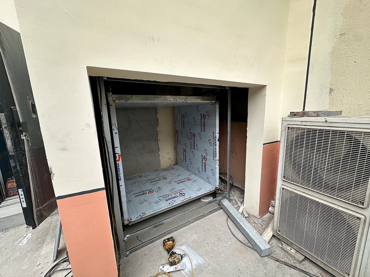
The dumbwaiter installation site was a two-storey restaurant with an existing brick service shaft behind the kitchen. No machine room, no spare riser, and a floor opening left over from a dumb waiter that had stopped working years earlier. The shaft measured 1,250 mm clear — enough for an 800 mm car once guide rails and their brackets were fitted, with roughly 70 mm of clearance each side.
That 70 mm is the number that decides the car on a brick-shaft dumbwaiter installation site. Guide rail brackets are not flat against the wall; they stand off by 40–60 mm depending on the rail size, and they have to be packed to plumb. A shaft measured at 1,150 mm would have forced a smaller car, and a shaft measured at 1,100 mm would have meant cutting the wall — which in a working kitchen means closing it.
What decided the specification
Peak tray load, not average. A restaurant does not send trays up at a steady rate; it sends them in bursts when a section of the dining room is served at once — service-volume patterns of the kind the National Restaurant Association tracks by covers per service. Three trays of plated food plus the bussing cart they sit on put the working load near 160 kg, which ruled out the 100 kg car before price was even discussed.
| Service pattern | Trays per hour | Peak trays waiting | Working load | Car that fits |
|---|---|---|---|---|
| À la carte lunch, 60 covers | 10–14 | 2 | 60–80 kg | 80×80×100 cm |
| Banquet service, 150 covers | 18–24 | 3 plus cart | 140–180 kg | 80×80×100 cm |
| Takeaway, concentrated dispatch | 6–9 | 2, heavier each | 90–110 kg | 70×70×100 cm |
The second deciding fact on this dumbwaiter installation site was the supply. Single-phase 220 V was already at the kitchen distribution board. A three-phase upgrade would have meant a new cable run through finished dining space, which costs more than the difference between the two motor options. The electrical question is covered in more detail in the dumbwaiter installation guide.
How it was installed
Rails and machine beam first, then the car frame assembled inside the shaft rather than on the landing. On this dumbwaiter installation site the landing is usually the only route between kitchen and dining room, so a car assembled on the floor and lifted in would have closed that route for most of a day. Assembling in the shaft keeps the landing usable and takes about the same total hours.
Commissioning was done outside service hours. The final checks — levelling at each floor, door interlock timing, the emergency lowering procedure — need the unit moving repeatedly, which is not something a full dining room tolerates. Details of that checklist are in the restaurant dumbwaiter installation guide.
Profile 2 — Hotel Linen and Room Service, Five Stops
Configuration: 100×100×120 cm car, 200–250 kg rated load, five stops, three-phase 380 V, traction drive.
The decisive condition at this dumbwaiter installation site is not the shaft, it is the cargo. Hotel service means two loads that do not mix: clean linen going up and food going to rooms. A linen trolley is typically 1,200 mm long and 800 mm wide, which is why the car jumps to 100×100 cm — a 80×80 cm car takes the trolley diagonally and nothing else. Rated load follows the trolley plus linen: 200–250 kg is the working range, and the 250 kg ceiling is what separates a hotel unit from a restaurant unit.
The design question that actually decides the outcome on a dumbwaiter installation site like this one is whether one car serves both duties. One car is cheaper and fits an existing shaft. Two cars cost roughly twice as much and need either a wider shaft or two shafts. If the building can only take one car, the workable compromise is a removable intermediate shelf and a cleaning regime between linen and food runs — not a partition, which gets left in place and turns a 1,200 mm car into a 500 mm one.
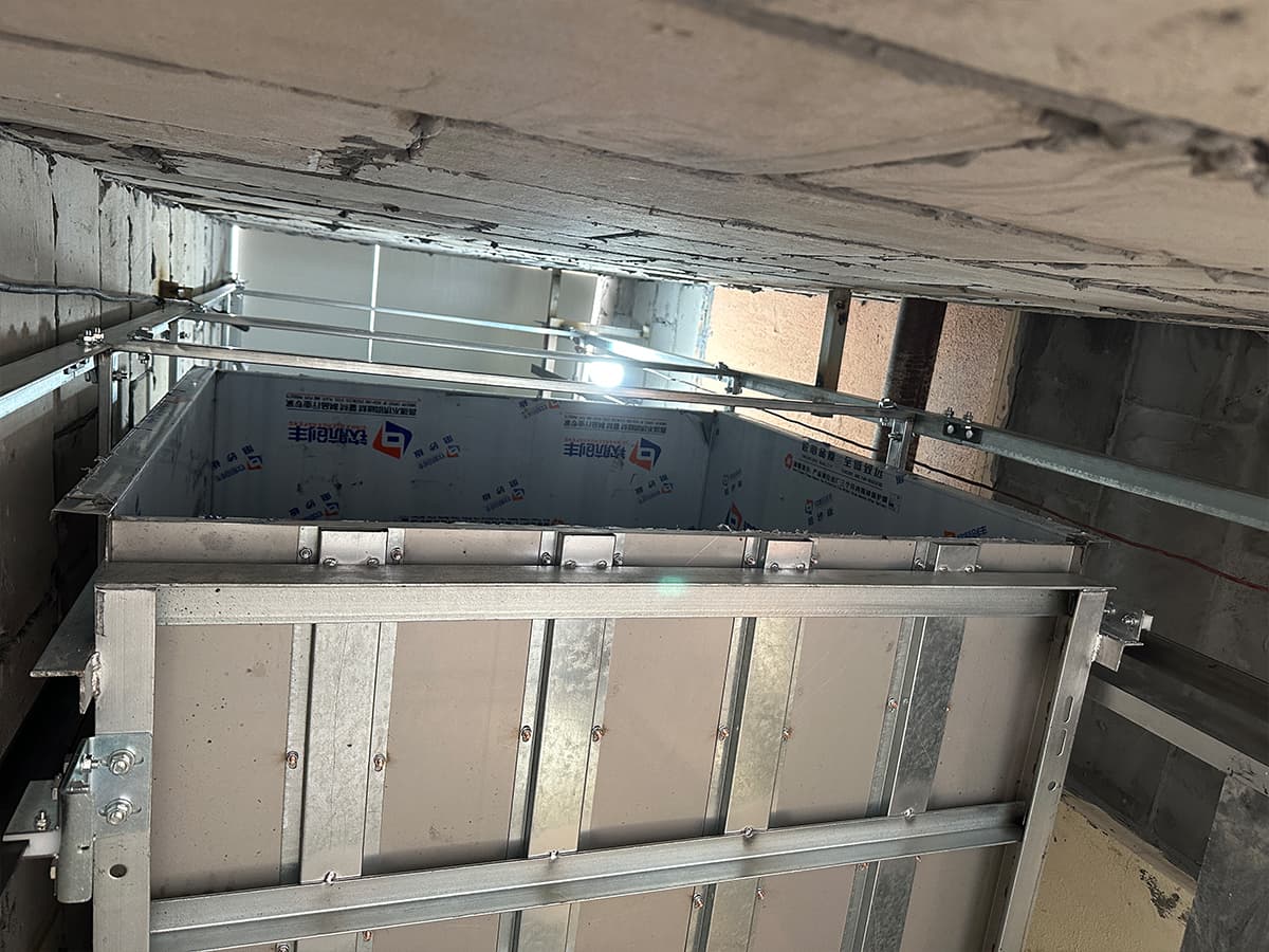
Five stops also changes the drive decision on a dumbwaiter installation site of this height. Above four stops, a traction unit with counterweight becomes the cheaper long-run option because the motor size stops growing with load; hydraulic units carry the whole load on the ram at every floor. On a dumbwaiter installation site with five or more stops, the shaft height also has to absorb a counterweight run, which is the single most common reason a hotel project loses its first shaft choice.
Profile 3 — Central Kitchen With Parallel Units
Configuration: 100×100×120 cm car, 200–250 kg rated load, two or three stops, three-phase 380 V, two or three units running in parallel.
A central kitchen dumbwaiter installation site is specified around the dispatch hour rather than the daily total, and it moves food in trolleys on a schedule, not on demand. One lift becomes the bottleneck at the dispatch hour, so the specification shifts from “what size” to “how many, and how do they fail”. Two units at 250 kg each move more than one unit at 500 kg and keep the kitchen running when one is down.
The three constraints that decide parallel units
- Supply capacity. Each control cabinet needs its own circuit. Three units on a shared 380 V feed will trip together under simultaneous acceleration, which is exactly when the kitchen needs them most.
- Shaft geometry. On a parallel dumbwaiter installation site each unit needs either one wide shaft with a dividing wall or two shafts with a structural gap. Retrofitting a second shaft into a finished building usually costs more than the second lift.
- Spare commonality. Two identical units share one set of spare parts. Two different units double the spares holding for no operational gain.
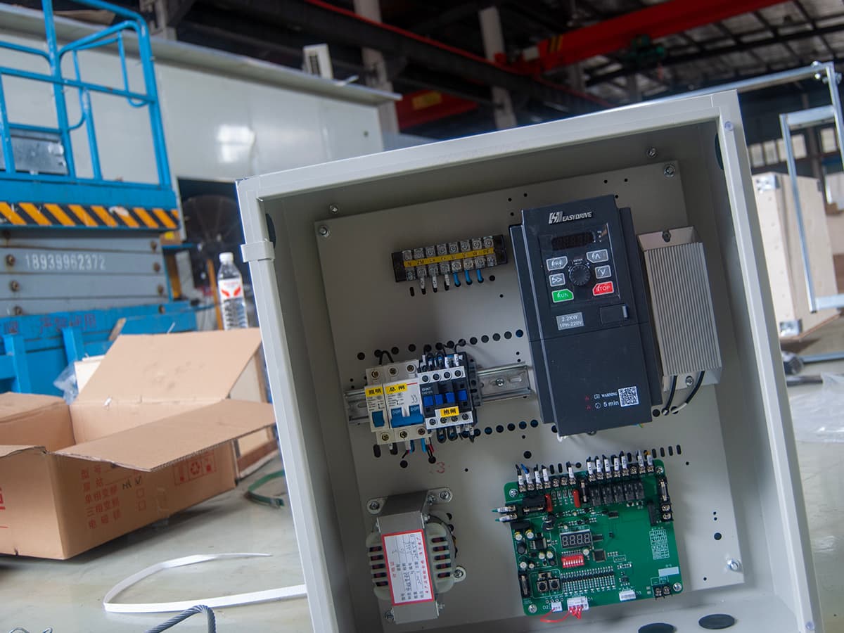
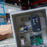
Control is where a parallel dumbwaiter installation site is usually under-specified. On a dumbwaiter installation site running two or more units, one cabinet per unit with a shared call circuit is the workable arrangement; a single cabinet driving two machines is not, because a fault takes both out. The cabinet below is the standard build for this type of dumbwaiter installation site — ABB variable frequency drive, Schneider breakers, one circuit per machine.
Profile 4 — Clinic, Care Home and Document Lift
Configuration: 60×60×80 cm car, 100 kg rated load, two or three stops, single-phase 220 V, traction drive.
The smallest dumbwaiter installation site profile is also the one most often over-specified. A clinic moving files, samples and pharmacy stock does not need 200 kg; it needs a car that fits an existing service riser. At 60×60×80 cm the shaft can be as small as 900 mm clear, which is why this size is the only one that regularly fits a riser left over from building services.
Two rules matter more than size on this type of dumbwaiter installation site. First, clean and dirty routes must not share a car — a document lift and a waste route in the same shaft is a licensing problem, not a design preference. Second, the door height matters more than the car height: an 800 mm opening takes a standard archive box, and going to 1,000 mm rarely helps because the box was never the constraint, the trolley was.
Where a dumbwaiter installation site has three stops and the building is a care home, the call stations need to be reachable at seated height and the car needs a light that stays on for the full travel time. These are small details that are cheap at order time and expensive after handover.
The Installation Sequence, Week by Week
On a dumbwaiter installation site the lead time is three separate clocks, and buyers who add them together wrongly are the ones who end up with a machine in a crate and a shaft that is not ready. Manufacturing runs 4–8 weeks, sea freight 2–3 weeks, and site work 1–2 weeks — but the shaft has to be finished before the site work begins, which means the civil work has to run inside the manufacturing window, not after it. A service shaft is planned with the rest of the building systems rather than added afterwards, which is how the Whole Building Design Guide treats it.
| Stage | Weeks | What happens | What the buyer must finish |
|---|---|---|---|
| Drawings and deposit | 1–2 | General arrangement drawing, shaft and power confirmation | Confirm shaft clear size, pit depth, headroom, supply |
| Manufacturing | 3–8 | Car, frame, rails, doors, control cabinet, test run | Cut the opening, build the pit, bring power to the cabinet position |
| Packing and freight | 9–11 | Crating, booking, sailing | Confirm landing access and crane or forklift availability |
| Site installation | 12–13 | Rails, machine, car, doors, wiring | Provide a dry store and a working hoist or lifting point |
| Commissioning and handover | 13–14 | Load test, levelling, interlocks, training, documents | Witness the load test, sign the handover sheet |
The row that causes most delays on a dumbwaiter installation site is the second one. A dumbwaiter installation site that is still being cut when the container lands can sit for a month, and storage at the port is charged by the day. The practical rule is to have the shaft finished and the power terminated one week before the vessel is scheduled to arrive, not on the day.
Six Site Problems That Delay Handover
The six problems below account for most of the dumbwaiter installation site delays we see. None of them is a manufacturing problem, and all of them are cheaper to fix before the order than after.
| Problem | What it does | How to prevent it |
|---|---|---|
| Shaft 50 mm narrow | Car drops one size, or rails get packed beyond plumb | Measure clear width at three heights, take the smallest |
| Pit shallower than 300 mm | Buffer and stop wiring will not fit; car cannot reach the bottom landing | Check pit at the four corners, not the centre |
| Headroom under 2,600 mm | Machine and overhead clearance fail; unit has to be reduced or relocated | Measure from finished floor to the lowest obstruction |
| Supply is 415 V or 60 Hz | Motor and drive need re-rating; delivery slips | Photograph the panel and the nameplate before ordering |
| No door reveal or frame allowance | Finished opening is smaller than the door, so the car is blocked | Agree the finished opening, not the structural one |
| Landing used as a material store | Doors and frame get damaged during other trades | Hand over the landing one week before installation, not on the day |
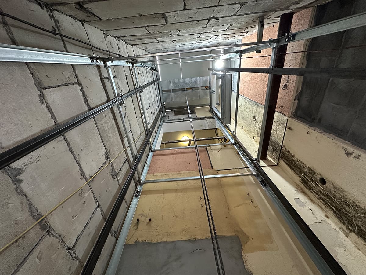
On any dumbwaiter installation site the first three are measurement errors, and they are the expensive ones, because they change the machine rather than the schedule. A shaft measured at three heights and at the four corners of the pit gives a number you can build to. A shaft measured once, at eye level, in the middle, gives a number that is wrong often enough to matter.
What Happens at the Factory Before the Container Leaves
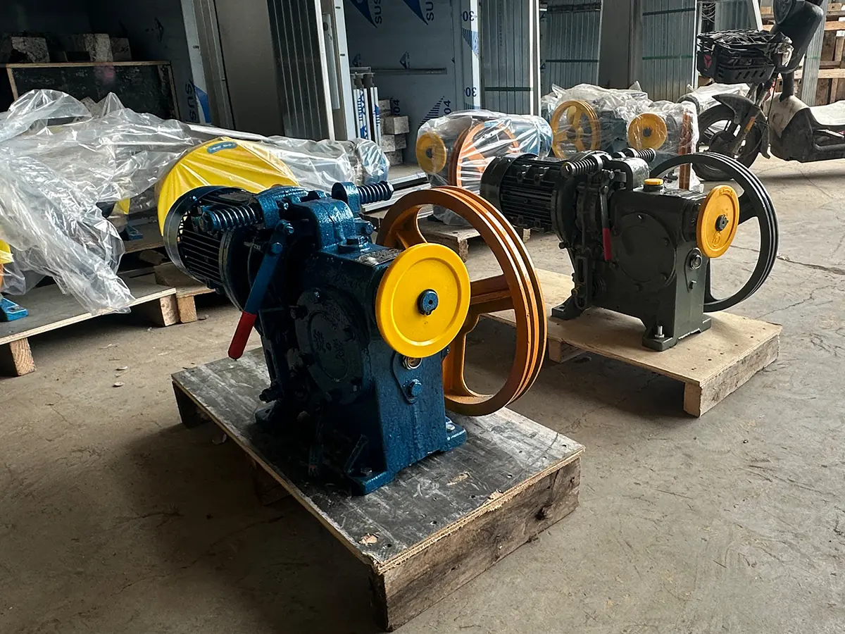
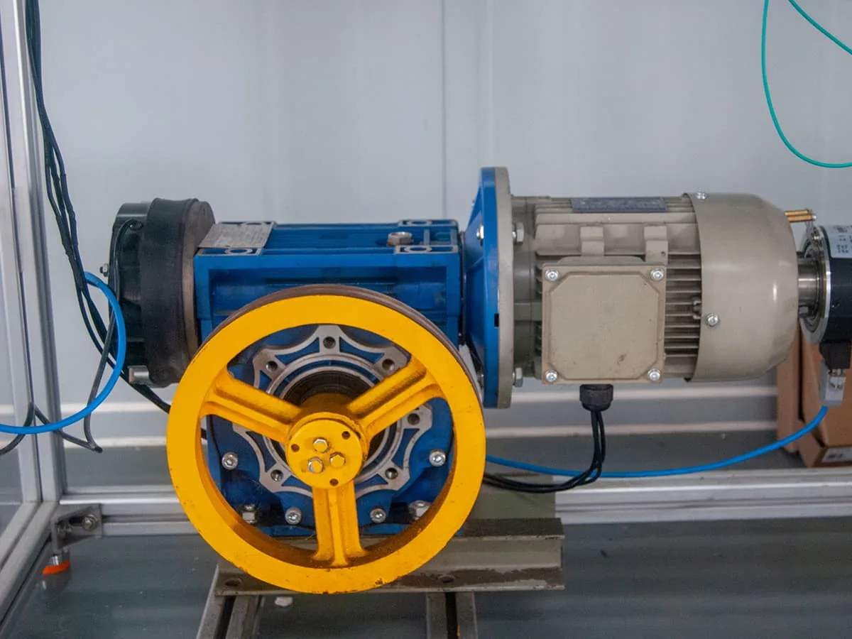
A dumbwaiter installation site problem that nobody photographs is the one that arrives already broken. Traction machines and control cabinets are tested before crating, because a dumbwaiter installation site cannot repair what arrives already broken, and the test is the part of the process buyers are least able to verify from a catalogue.
What a test record should contain
A test record that is worth asking for contains four things: the serial number of the machine, the load applied and for how long, the measured brake stopping distance, and the name of the person who signed it. A record with only a tick box and no load figure is a photograph of a form, not a test.
Two checks are done on every unit before packing. The first is a run at 125 % of rated load for the brake, which is the figure most standards use for a periodic verification test rather than a routine one — doing it at the factory is cheaper than doing it on site. The second is a full travel run at each landing to set the slowdown points, because those are set against the actual rail positions and cannot be pre-set accurately on a bench.
ServLifts is the service-lift brand of Suzhou Bsite Express Elevator Co., Ltd. Every unit in these photographs was built and tested in Wujiang, Suzhou, on the Yangtze delta, and shipped from there. That is the whole of the supply chain — there is no third-party assembler between the factory floor and the container.

What to Send Us for a Real Configuration
Six items produce a quotation that will not change on any dumbwaiter installation site. Without them the answer is a range, and a range is what a competitor uses to undercut you on paper and lose you a month later.
| Item | What we need | Why it decides the machine |
|---|---|---|
| Shaft clear size | Width and depth, smallest of three heights | Sets the car size; 50 mm decides one size down |
| Pit depth | Floor to pit floor, four corners | Buffer, stop wiring and bottom landing approach |
| Headroom | Top finished floor to lowest obstruction | Machine position and overhead clearance |
| Stops and travel | Number of stops, floor-to-floor heights | Rope length, counterweight run, drive choice |
| Load | Rated load or the actual goods carried | Car size, frame, and the 150/200/250 kg step |
| Power | Voltage, phases, frequency, breaker size | Motor, drive and cabinet; wrong supply delays delivery |
Send those six, plus a photograph of the shaft taken from the bottom landing looking up, and the answer that comes back will be a drawing rather than a price range. If the building is still at design stage, the guide to choosing a dumbwaiter for a restaurant or hotel sets out which decisions have to be made first.
The short version. A dumbwaiter installation site is four measurements and one electrical fact. Car size and rated load follow from the shaft and the peak load, the drive follows from the number of stops, and the lead time follows from whether the shaft is finished before the container lands. Get those in the right order and the four profiles above cover most of what a building can throw at you.
If your dumbwaiter installation site does not match any of the four — too narrow, too shallow, or with a headroom problem — that is the dumbwaiter installation site worth sending to us before anything is ordered. Send the six measurements and we will tell you which profile is closest and what has to change. For the wider picture of what a dumbwaiter is and where it fits, see what is a dumbwaiter elevator; for cost structure rather than site work, the dumbwaiter price guide covers the budget side.
For buyers comparing suppliers rather than sites, two pages go deeper: dumbwaiter manufacturer in China covers how to qualify a factory, and China dumbwaiter factory covers what happens inside one. If the question is drive type rather than site geometry, the dumbwaiter control system page explains what the cabinet in Profile 3 is actually doing.
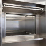
[…] a corridor niche in a clinic. How those constraints resolve in practice is the subject of these dumbwaiter installation site profiles, which show the shaft size, load rating and door layout that four common project types end up […]
[…] and door layout. If you would rather see those combinations as complete site pictures first, the dumbwaiter installation sites for four project types page sets them out against the same constraints covered […]
[…] problems of shaft size, load rating and door layout differently. Four worked examples of these dumbwaiter installation sites show how the specification in section 5 shifts from one building type to the […]